Page: 1
/
13
Total 65 questions
Master JN0-481: Juniper Data Center Specialist Certification Made Simple
Question 1
You are allowed to assign tags for which three objects? (Choose three.)
Correct : A, B, C
In Juniper Apstra 5.1, tags are a lightweight metadata mechanism used to classify objects and enable conditional automation (for example, driving dynamic configlets or simplifying filtering/searching in the UI). Apstra supports tagging several blueprint-operational objects that commonly participate in day-1/day-2 workflows.
Virtual networks can be tagged so operators can group, search, and apply automation consistently across sets of segments. This is useful in EVPN-VXLAN fabrics where virtual networks represent VLAN- or VXLAN-backed broadcast domains and you may want policies or configlet logic to apply to all ''finance'' or ''pci'' segments as a group.
Interfaces can be tagged directly within a blueprint (for example, leaf access ports, uplinks, or specific border-facing ports). Interface tags are often used to drive template-based configuration behavior and to simplify operational actions across many ports without relying on fragile naming conventions.
Generic systems (internal or external) can also be tagged. Apstra documentation explicitly describes using tags to specify roles for internal generic systems, enabling you to differentiate server types or attachment roles and then apply the correct intent (connectivity templates, VN attachments, or policies) in a repeatable way.
By contrast, property sets are structured data objects used for parameterization (YAML/JSON values for templates/probes), and device profiles describe hardware/NOS capabilities; they are not the standard blueprint objects for tag assignment in this scenario.
Verified Juniper sources (URLs):
https://www.juniper.net/documentation/us/en/software/apstra5.1/apstra-user-guide/topics/task/tag-virtual-network-update.html
https://www.juniper.net/documentation/us/en/software/apstra5.1/apstra-user-guide/topics/topic-map/tag-interface-add-remove-datacenter.html
https://www.juniper.net/documentation/us/en/software/apstra5.1/apstra-user-guide/topics/topic-map/internal-generic-system-create.html
Start a Discussions
Submit Your Answer:
Question 2
You want to gracefully take a device out of service to perform an OS upgrade. How would you accomplish this task using Juniper Apstra?
Correct : B
In Apstra 5.1, the correct operational method to gracefully remove a switch from service for maintenance is to set its Deploy Mode to Drain. Drain is a day-2 operational control that tells Apstra to adjust intent so the fabric can continue operating while the targeted device is logically taken out of service as much as the design allows. This is especially relevant in EVPN-VXLAN leaf-spine fabrics where taking down a spine or a leaf can disrupt underlay BGP adjacencies and overlay reachability if traffic is not shifted first.
This action is performed from the blueprint's Active view because Drain affects the currently deployed, running fabric state (not a staged design change). Selecting the device under Active and changing Deploy Mode to Drain initiates the workflow that prepares the device for maintenance by reducing its role in forwarding and/or withdrawing dependent services according to the blueprint's modeled redundancy (for example, shifting server-facing traffic to an MLAG/ESI peer where applicable, or reducing reliance on the device for transit). After the device is drained, an OS upgrade can be performed with less impact, and the device can later be returned to service by switching Deploy Mode back to Deploy and committing the change.
The ''Upgrade'' action is not the deploy-mode mechanism described for graceful removal; the key is Deploy Mode Drain from Active, which is explicitly intended for maintenance and decommissioning scenarios.
Verified Juniper sources (URLs):
https://www.juniper.net/documentation/us/en/software/apstra5.1/apstra-user-guide/topics/task/device-drain.html
https://www.juniper.net/documentation/us/en/software/apstra4.2/apstra-drain-mode/apstra-drain-mode-guide/topics/concept/apstra-drain-mode-activate-or-disable-drain.html
Start a Discussions
Submit Your Answer:
Question 3
Using Juniper Apstr
a. which component is defined in a template?
Correct : A
According to the Juniper documentation1, a template is a configuration template that defines a network's policy intent and structure. A template can be either rack-based or pod-based, depending on the type and number of racks and pods in the network design. A template includes the following details:
Policies: These are the parameters that apply to the entire network, such as the overlay control protocol, the ASN allocation scheme, and the underlay type.
Structure: This is the physical layout of the network, such as the type and number of racks, pods, spines, and leaves. The structure also defines the leaf-to-spine interconnection, which is the number and type of links between the leaf and spine devices. The leaf-to-spine interconnection can be either single or dual, depending on the redundancy and bandwidth requirements.
Therefore, the correct answer is A. the leaf-to-spine interconnection. This is a component that is defined in a template, as it determines the physical connectivity of the network. The speed of the links, the number of spine devices, and the definition of IP pools are not components that are defined in a template, as they are either derived from the device profiles, the resource pools, or the blueprint settings.Reference:Templates Introduction | Apstra 4.2 | Juniper Networks
Start a Discussions
Submit Your Answer:
Question 4
You want to assign resources to your blueprint during the deployment phase. In this scenario, which statement is correct?
Correct : D
In Apstra 5.1, ''resources'' (such as ASNs, IP addressing, and VNIs) are allocated to blueprint elements using resource pools. The blueprint does not require you to manually craft every individual resource value; instead, Apstra's workflow is to have you indicate which pool(s) should be used for the blueprint, and then Apstra automatically pulls and assigns the required values. This automation is fundamental to Apstra's intent-based model: once the blueprint knows which pools to consume, it can deterministically allocate unique values across the fabric and generate consistent Junos configuration for the assigned devices.
Option D best matches this behavior because it reflects the documented mechanism: required resources are automatically pulled from the selected pool(s) and assigned in a fast, bulk transaction. This is what enables repeatable deployments---especially in EVPN-VXLAN data center fabrics---because resource collisions and manual tracking are avoided.
Option A is not the defining prerequisite for resource assignment; device profile and device assignment are important overall build steps, but the correctness of resource assignment is tied to pool selection and availability rather than being strictly gated by those tasks. Option B is incorrect because pools can be created and managed beyond only ''global'' contexts, and Apstra also supports creating additional pools from within the blueprint when needed. Option C is misleading because resources are governed by pools and allocation, not only by manual creation under a single tab.
Verified Juniper sources (URLs):
https://www.juniper.net/documentation/us/en/software/apstra5.1/apstra-user-guide/topics/concept/resources.html
https://www.juniper.net/documentation/us/en/software/apstra5.1/apstra-user-guide/topics/concept/freeform-resource-management.html
https://www.juniper.net/documentation/us/en/software/apstra5.1/apstra-user-guide/topics/ref/resource-pools-api.html
Start a Discussions
Submit Your Answer:
Question 5
Exhibit.
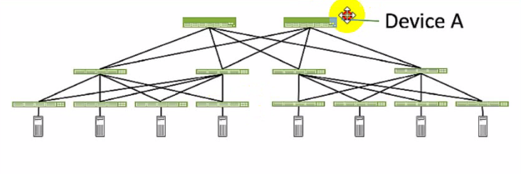
Referring to the exhibit, which role does Device A serve in an IP fabric?
Correct : B
Device A serves as a spine in an IP fabric. An IP fabric is a network architecture that uses a spine-leaf topology to provide high performance, scalability, and reliability for data center networks. A spine-leaf topology consists of two layers of devices: spine devices and leaf devices. Spine devices are the core devices that interconnect all the leaf devices using equal-cost multipath (ECMP) routing. Leaf devices are the edge devices that connect to the servers, storage, or other network devices. In the exhibit, Device A is connected to four leaf devices using multiple links, which indicates that it is a spine device. The other options are incorrect because:
A . leaf is wrong because a leaf device is an edge device that connects to the servers, storage, or other network devices. In the exhibit, Device A is not connected to any servers, storage, or other network devices, but only to four leaf devices, which indicates that it is not a leaf device.
C . super spine is wrong because a super spine device is a higher-level device that interconnects multiple spine devices in a large-scale IP fabric. A super spine device is typically used when the number of leaf devices exceeds the port density of a single spine device. In the exhibit, Device A is not connected to any other spine devices, but only to four leaf devices, which indicates that it is not a super spine device.
D . server is wrong because a server device is a compute or storage device that connects to a leaf device in an IP fabric. A server device is typically the end host that provides or consumes data in the network. In the exhibit, Device A is not connected to any leaf devices, but only to four leaf devices, which indicates that it is not a server device.Reference:
IP Fabric Underlay Network Design and Implementation
IP Fabric Overview
IP Fabric Architecture
Start a Discussions
Submit Your Answer:
Want to Unlock Everything for
Juniper JN0-481 Exam?
Juniper JN0-481 Exam?
By upgrading to Premium Access, you’ll instantly unlock:
Unlock 65 Premium Questions
- Exam Name: Data Center, Specialist
- Exam Code: JN0-481
- Last Update: 13-Jul-2026
- Formats: PDF, Web-based,
Desktop Practice - 24/7 Customer Support
 Price: $59 (PDF Format)