Page: 1
/
4
Total 16 questions
Master VMware NSX-T 3.x Like a Pro: Ace Your 3V0-41.22 Exam!
Question 1
SIMULATION
Task 1
You are asked to prepare a VMware NSX-T Data Center ESXi compute cluster Infrastructure. You will prepare two ESXi servers in a cluster for NSX-T overlay and VLAN use.
All configuration should be done using the NSX UI.
* NOTE: The configuration details in this task may not be presented to you in the order in which you must complete them.
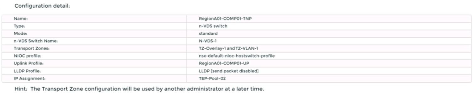
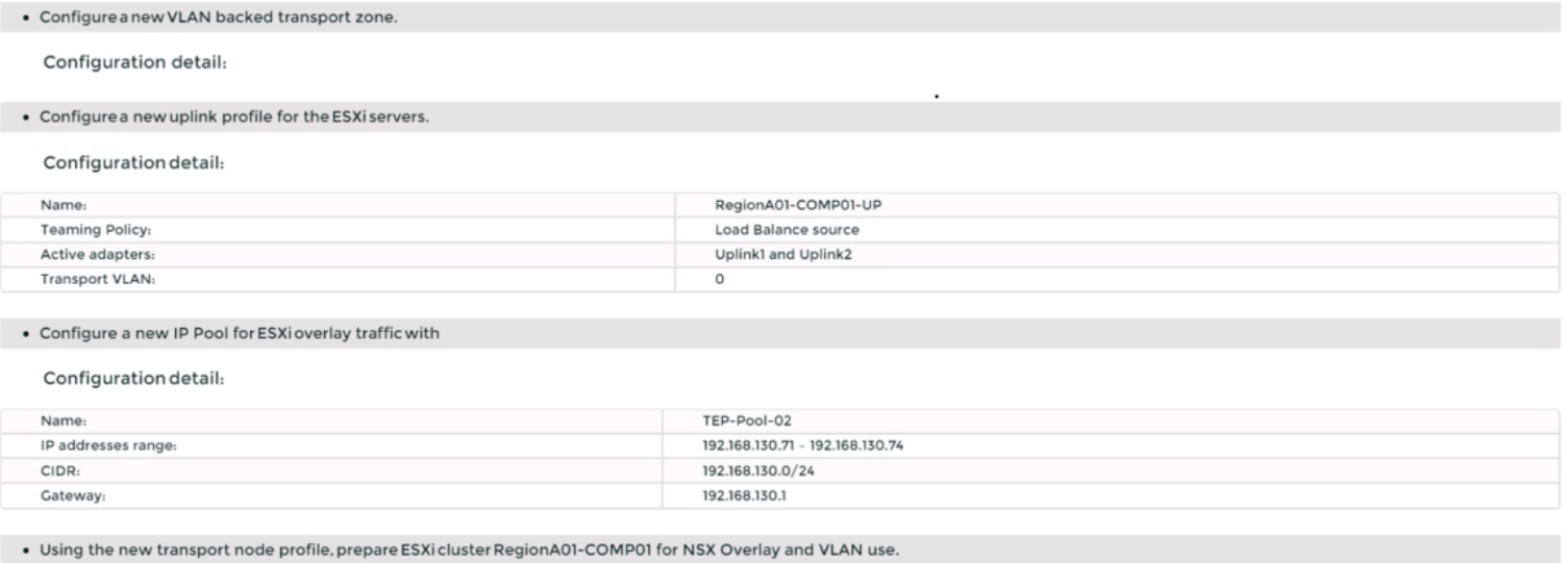
* Configure a new Transport Node profile and add one n-VDS switch. Ensure Uplink 1 and Uplink 2 of your configuration use vmnic2 and vmnic3 on the host.
Complete the requested task.
NOTE: Passwords are contained in the user_readme.txt. Configuration details may not be provided in the correct sequential order. Steps to complete this task must be completed in the proper order. Other tasks are dependent on the completion Of this task. You may want to move to other tasks/steps while waiting for configuration changes to be applied. This task should take approximately 20 minutes to complete.
Correct : A
To prepare a VMware NSX-T Data Center ESXi compute cluster infrastructure, you need to follow these steps:
Log in to the NSX Manager UI with admin credentials. The default URL is https://<nsx-manager-ip-address>.
Navigate to System > Fabric > Profiles > Transport Node Profiles and click Add Profile.
Enter a name and an optional description for the transport node profile.
In the Host Switches section, click Set and select N-VDS as the host switch type.
Enter a name for the N-VDS switch and select the mode as Standard or Enhanced Datapath, depending on your requirements.
Select the transport zones that you want to associate with the N-VDS switch. You can select one overlay transport zone and one or more VLAN transport zones.
Select an uplink profile from the drop-down menu or create a custom one by clicking New Uplink Profile.
In the IP Assignment section, select Use IP Pool and choose an existing IP pool from the drop-down menu or create a new one by clicking New IP Pool.
In the Physical NICs section, map the uplinks to the physical NICs on the host. For example, map Uplink 1 to vmnic2 and Uplink 2 to vmnic3.
Click Apply and then click Save to create the transport node profile.
Navigate to System > Fabric > Nodes > Host Transport Nodes and click Add Host Transport Node.
Select vCenter Server as the compute manager and select the cluster that contains the two ESXi servers that you want to prepare for NSX-T overlay and VLAN use.
Select the transport node profile that you created in the previous steps and click Next.
Review the configuration summary and click Finish to start the preparation process.
Start a Discussions
Submit Your Answer:
Question 2
SIMULATION
Task 2
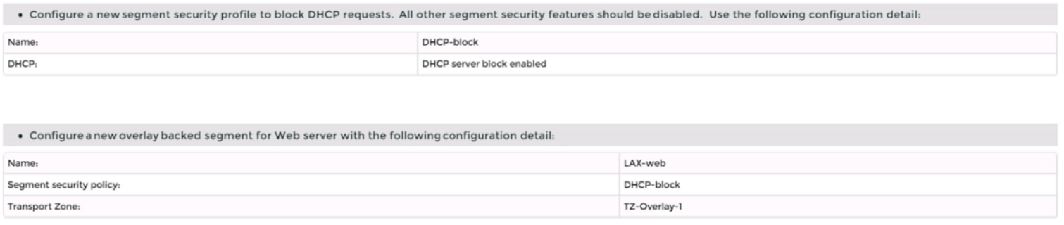
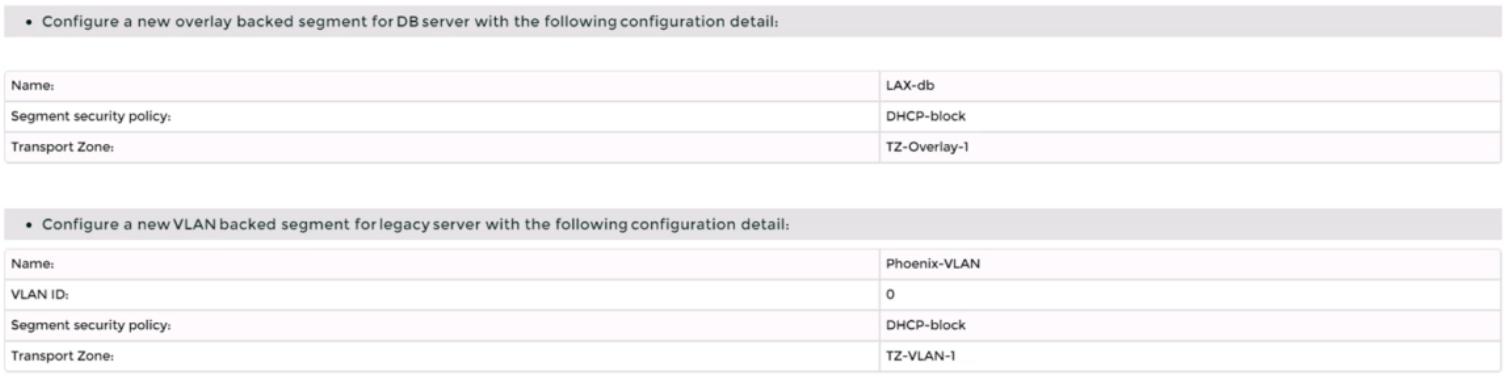
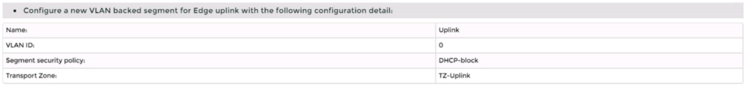
You are asked to deploy three Layer 2 overlay-backed segments to support a new 3-tier app and one Layer 2 VLAN-backed segment for support of a legacy application. The logical segments must block Server DHCP requests. Ensure three new overlay-backed segments and one new VLAN-backed logical segment are deployed to the RegionA01-COPMOI compute cluster. All configuration should be done utilizing the NSX UI.
You need to:
Complete the requested task.
Notes: Passwords are contained in the user_readme.txt. Task 2 is dependent on the completion of Task 1. Other tasks are dependent on completion of this task. You may want to move to the next tasks while waiting for configuration changes to be applied. This task should take approximately 10 minutes to complete.
Correct : A
To deploy three layer 2 overlay-backed segments and one layer 2 VLAN-backed segment, you need to follow these steps:
Log in to the NSX Manager UI with admin credentials. The default URL is https://<nsx-manager-ip-address>.
Navigate to Networking > Segments and click Add Segment.
Enter a name for the segment, such as Web-01.
Select Tier-1 as the connectivity option and choose an existing tier-1 gateway from the drop-down menu or create a new one by clicking New Tier-1 Gateway.
Enter the gateway IP address of the subnet in a CIDR format, such as 192.168.10.1/24.
Select an overlay transport zone from the drop-down menu, such as Overlay-TZ.
Optionally, you can configure advanced settings such as DHCP, Metadata Proxy, MAC Discovery, or QoS for the segment by clicking Set Advanced Configs.
Click Save to create the segment.
Repeat steps 2 to 8 for the other two overlay-backed segments, such as App-01 and DB-01, with different subnet addresses, such as 192.168.20.1/24 and 192.168.30.1/24.
To create a VLAN-backed segment, click Add Segment again and enter a name for the segment, such as Legacy-01.
Select Tier-0 as the connectivity option and choose an existing tier-0 gateway from the drop-down menu or create a new one by clicking New Tier-0 Gateway.
Enter the gateway IP address of the subnet in a CIDR format, such as 10.10.10.1/24.
Select a VLAN transport zone from the drop-down menu, such as VLAN-TZ, and enter the VLAN ID for the segment, such as 100.
Optionally, you can configure advanced settings such as DHCP, Metadata Proxy, MAC Discovery, or QoS for the segment by clicking Set Advanced Configs.
Click Save to create the segment.
To apply a segment security profile to block DHCP requests on the segments, navigate to Networking > Segments > Segment Profiles and click Add Segment Profile.
Select Segment Security as the profile type and enter a name and an optional description for the profile.
Toggle the Server Block and Server Block - IPv6 buttons to enable DHCP filtering for both IPv4 and IPv6 traffic on the segments that use this profile.
Click Save to create the profile.
Navigate to Networking > Segments and select the segments that you want to apply the profile to.
Click Actions > Apply Profile and select the segment security profile that you created in step 18.
Click Apply to apply the profile to the selected segments.
Start a Discussions
Submit Your Answer:
Question 3
SIMULATION
Task 6
You are asked to integrate NSX manager with LDAP to better control NSX administrators' roles and responsibilities. Ensure users can manage the NSX environment utilizing Active Directory login credentials.
You need to:
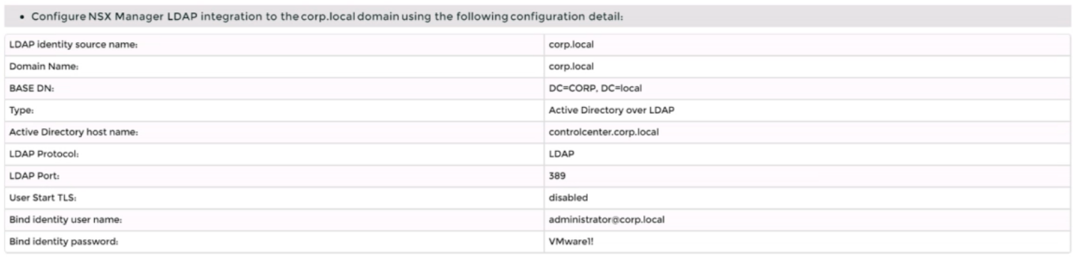
* Configure NSX Manager LDAP integration to the corp.local domain using the following configuration detail:
* Configure the user nsx-admin@corp.local Active Directory account as an Enterprise Admin access role.
Complete the requested task.
Notes:
Passwords are contained in the user_readme.txt. You may want to move to other tasks/steps while waiting for configuration changes to be applied. This task should take approximately 15 minutes to complete.
Correct : A
To integrate NSX Manager with LDAP to better control NSX administrators' roles and responsibilities, you need to follow these steps:
Log in to the NSX Manager UI with admin credentials. The default URL is https://<nsx-manager-ip-address>.
Navigate to System > User Management > LDAP and click Add Identity Source.
Enter a name for the identity source, such as corp.local.
Enter the domain name of your Active Directory server, such as DC=corp,DC=local.
Select Active Directory over LDAP as the type from the drop-down menu.
Click Set to configure LDAP servers. You can add up to three LDAP servers for failover support, to each domain.
Enter the hostname or IP address of your LDAP server, such as corpdcserver.corp.local.
Select LDAP as the protocol from the drop-down menu.
Enter the port number for the LDAP server, such as 389.
Click Connection Status to test the connection to the LDAP server. If successful, you will see a green check mark and a message saying ''Connection successful''.
Optionally, you can enable StartTLS to use encryption for the LDAP connection. To do this, toggle the Use StartTLS button and enter the certificate of the LDAP server in PEM format in the text box below.
Click Save to add the LDAP server.
Repeat steps 6 to 12 to add more LDAP servers if needed.
Enter the bind entry user name and password for the LDAP server, such as Administrator@corp.local and VMware1!.
Click Save to create the identity source.
Navigate to System > User Management > Users and Roles and click Add Role Assignment for LDAP.
Select corp.local as the domain from the drop-down menu.
Enter nsx-admin@corp.local in the search box and select it from the list that appears.
Select Enterprise Admin as the role from the drop-down menu.
Click Save to assign the role to the user.
Start a Discussions
Submit Your Answer:
Question 4
SIMULATION
Task 3
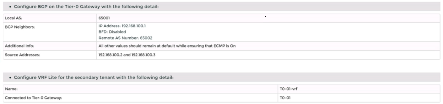
You are asked to deploy a new instance of NSX-T into an environment with two isolated tenants. These tenants each have separate physical data center cores and have standardized on BCP as a routing protocol.
You need to:
Complete the requested task.
Notes: Passwords are Contained in the user_readme.txt. Task 3 is dependent on the Completion Of Task and 2. Other tasks are dependent On the Completion Of this task. Do not wait for configuration changes to be applied in this task as processing may take up to 10 minutes to complete. Check back on completion. This task should take approximately 10 minutes to complete.
Correct : A
To deploy a new instance of NSX-T into an environment with two isolated tenants, you need to follow these steps:
Log in to the NSX Manager UI with admin credentials. The default URL is https://<nsx-manager-ip-address>.
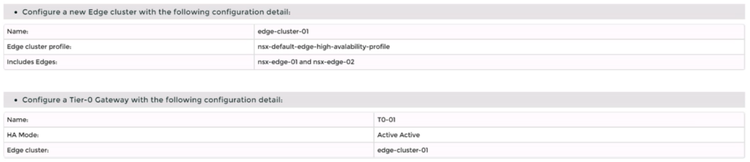
Navigate to System > Fabric > Nodes > Edge Transport Nodes and click Add Edge VM.
Enter a name and an optional description for the edge VM. Select the compute manager, cluster, and resource pool where you want to deploy the edge VM. Click Next.
Select the deployment size and form factor for the edge VM. For this task, you can select Medium as the size and VM as the form factor. Click Next.
Select the datastore and folder where you want to store the edge VM files. Click Next.
Configure the management network settings for the edge VM. Enter a hostname, a management IP address, a default gateway, a DNS server, and a domain search list. Optionally, you can enable SSH and join the edge VM to a domain. Click Next.
Configure the transport network settings for the edge VM. Select an N-VDS as the host switch type and enter a name for it. Select an uplink profile from the drop-down menu or create a new one by clicking New Uplink Profile. Map the uplinks to the physical NICs on the edge VM. For example, map Uplink 1 to fp-eth0 and Uplink 2 to fp-eth1. Optionally, you can configure IP assignment, MTU, or LLDP for the uplinks. Click Next.
Review the configuration summary and click Finish to deploy the edge VM.
Repeat steps 2 to 8 to deploy another edge VM for redundancy.
Navigate to Networking > Tier-0 Gateway and click Add Gateway > VRF.
Enter a name and an optional description for the VRF gateway. Select an existing tier-0 gateway as the parent gateway or create a new one by clicking New Tier-0 Gateway.
Click VRF Settings and enter a VRF ID for the tenant. Optionally, you can enable EVPN settings if you want to use EVPN as the control plane protocol for VXLAN overlay networks.
Click Save to create the VRF gateway.
Repeat steps 10 to 13 to create another VRF gateway for the second tenant with a different VRF ID.
Navigate to Networking > Segments and click Add Segment.
Enter a name and an optional description for the segment. Select VLAN as the connectivity option and enter a VLAN ID for the segment. For example, enter 128 for Tenant A's first uplink VLAN segment.
Select an existing transport zone from the drop-down menu or create a new one by clicking New Transport Zone.
Click Save to create the segment.
Repeat steps 15 to 18 to create three more segments for Tenant A's second uplink VLAN segment (VLAN ID 129) and Tenant B's uplink VLAN segments (VLAN ID 158 and 159).
Navigate to Networking > Tier-0 Gateway and select the VRF gateway that you created for Tenant A.
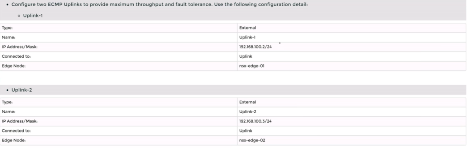
Click Interfaces > Set > Add Interface.
Enter a name and an optional description for the interface.
Enter the IP address and mask for the external interface in CIDR format, such as 10.10.10.1/24.
In Type, select External.
In Connected To (Segment), select the VLAN segment that you created for Tenant A's first uplink VLAN segment (VLAN ID 128).
Select an edge node where you want to attach the interface, such as Edge-01.
Enter the Access VLAN ID from the list as configured for the segment, such as 128.
Click Save and then Close.
Repeat steps 21 to 28 to create another interface for Tenant A's second uplink VLAN segment (VLAN ID 129) on another edge node, such as Edge-02.
Repeat steps 20 to 29 to create two interfaces for Tenant B's uplink VLAN segments (VLAN ID 158 and 159) on each edge node using their respective VRF gateway and IP addresses.
Verify that BGP sessions are established between each VRF gateway and its physical router neighbors using NSX UI or CLI commands . You can also check the routing tables and BGP statistics on each device .
You have successfully deployed a new instance of NSX-T into an environment with two isolated tenants using VRF Lite and BGP.
Start a Discussions
Submit Your Answer:
Question 5
SIMULATION
Task 4
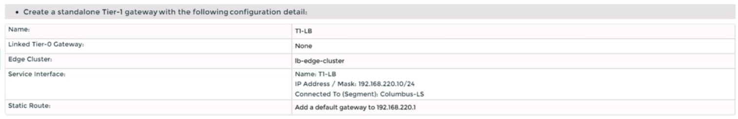
You are tasked with creating a logical load balancer for several web servers that were recently deployed.
You need to:

Complete the requested task.
Notes:
Passwords are contained in the user_readme.txt. Do not wait for configuration changes to be applied in this task as processing may take some time to complete. This task should take up to 35 minutes to complete and is required for subsequent tasks.
Correct : A
To create a logical load balancer for several web servers, you need to follow these steps:
Log in to the NSX Manager UI with admin credentials. The default URL is https://<nsx-manager-ip-address>.
Navigate to Networking > Load Balancing > Load Balancers and click Add Load Balancer.
Enter a name and an optional description for the load balancer. Select the tier-1 gateway where you want to attach the load balancer from the drop-down menu or create a new one by clicking New Tier-1 Gateway. Click Save.
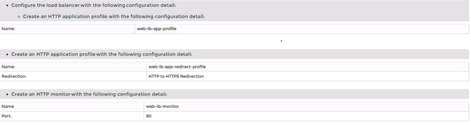
Navigate to Networking > Load Balancing > Application Profiles and click Add Application Profile.
Enter a name and an optional description for the application profile. Select HTTP as the application type from the drop-down menu. Optionally, you can configure advanced settings such as persistence, X-Forwarded-For, SSL offloading, etc., for the application profile. Click Save.
Navigate to Networking > Load Balancing > Monitors and click Add Monitor.
Enter a name and an optional description for the monitor. Select HTTP as the protocol from the drop-down menu. Optionally, you can configure advanced settings such as interval, timeout, fall count, rise count, etc., for the monitor. Click Save.
Navigate to Networking > Load Balancing > Server Pools and click Add Server Pool.
Enter a name and an optional description for the server pool. Select an existing application profile from the drop-down menu or create a new one by clicking New Application Profile. Select an existing monitor from the drop-down menu or create a new one by clicking New Monitor. Optionally, you can configure advanced settings such as algorithm, SNAT translation mode, TCP multiplexing, etc., for the server pool. Click Save.
Click Members > Set > Add Member and enter the IP address and port number of each web server that you want to add to the server pool. For example, enter 192.168.10.10:80 and 192.168.10.11:80 for two web servers listening on port 80. Click Save and then Close.
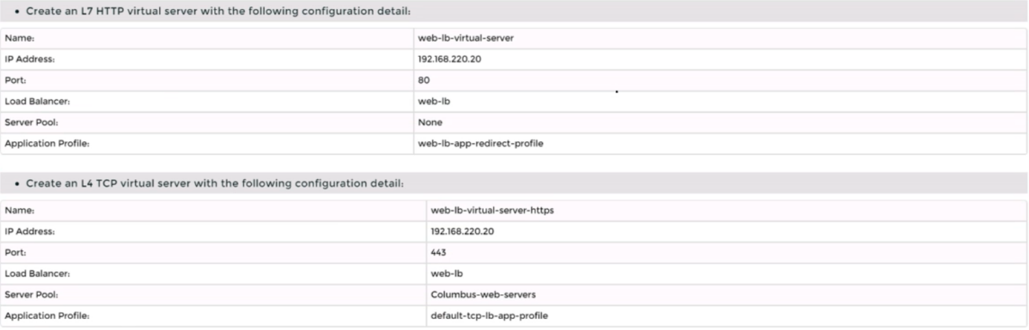
Navigate to Networking > Load Balancing > Virtual Servers and click Add Virtual Server.
Enter a name and an optional description for the virtual server. Enter the IP address and port number of the virtual server that will receive the client requests, such as 10.10.10.100:80. Select HTTP as the service profile from the drop-down menu or create a new one by clicking New Service Profile. Select an existing server pool from the drop-down menu or create a new one by clicking New Server Pool. Optionally, you can configure advanced settings such as access log, connection limit, rate limit, etc., for the virtual server. Click Save.
Start a Discussions
Submit Your Answer:
Want to Unlock Everything for
VMware 3V0-41.22 Exam?
VMware 3V0-41.22 Exam?
By upgrading to Premium Access, you’ll instantly unlock:
Unlock 16 Premium Questions
- Exam Name: Advanced Deploy VMware NSX-T Data Center 3.x
- Exam Code: 3V0-41.22
- Last Update: 26-Mar-2026
- Formats: PDF, Web-based,
Desktop Practice - 24/7 Customer Support
 Price: $59 (PDF Format)